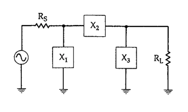
This network is called Pi as it resembles the Greek letter π. In this design, two L shaped networks are located close to each other back to back and can be used when (RS,RL)>100 Ω. At the intersection of two L-shaped networks, a single virtual resistance is considered for this design. The minus values in the figure is indicating the Xs and Xp are opposite type of reactance. For example if Xs is capacitor the Xp is inductor and vice versa. The virtual resistor is smaller than RL and RS [1].


The Q of the Pi matching network can be achieved as:

![]()
Then the movement between load and source will be divided into two sections.
From load to virtual resistor (because the load impedance is larger than source impedance.)

From virtual resistor towards the source:

The arrangement of the designed Pi network can be like each of these below structures and the selection of them depends on [1]:


If you want to see this impedance matching technique of the first mentioned Pi network on the Smith chart, follow the steps below:


[1] https://my.ece.utah.edu/~ece5321/4796_001.pdf
Need to understand the matching range of your matching unit?
Click on the link below to see how you can map the matching range of your matching unit quickly and easily.